ESP32 mit Arduino: Unterschied zwischen den Versionen
Keine Bearbeitungszusammenfassung |
Keine Bearbeitungszusammenfassung |
||
| Zeile 1: | Zeile 1: | ||
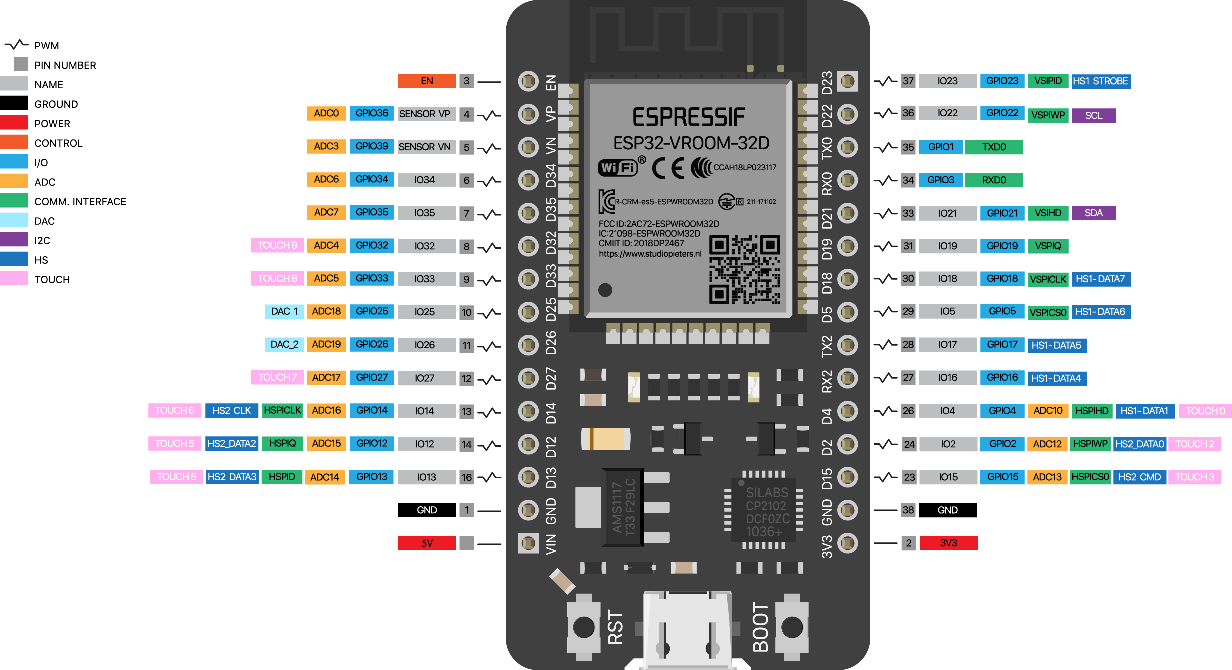
ESP32 Devboard 38pin version: | |||
https://raw.githubusercontent.com/AchimPieters/esp32-homekit-camera/master/Images/ESP32-30PIN-DEVBOARD.png | |||
=Programming the ESP32 Devboard from the Arduino IDE= | |||
Um den "ESP 32 Dev Module" programieren zu können müsst ihr in Arduino folgende schritte machen: | Um den "ESP 32 Dev Module" programieren zu können müsst ihr in Arduino folgende schritte machen: | ||
| Zeile 63: | Zeile 68: | ||
// Note: ADC2 pins cannot be used when Wi-Fi is used. So, if you’re using Wi-Fi and you’re having trouble getting the value from an ADC2 GPIO, you may consider using an ADC1 GPIO instead, that should solve your problem. | // Note: ADC2 pins cannot be used when Wi-Fi is used. So, if you’re using Wi-Fi and you’re having trouble getting the value from an ADC2 GPIO, you may consider using an ADC1 GPIO instead, that should solve your problem. | ||
===example: Spaghettimonster_Serial=== | ===example: Spaghettimonster_Serial=== | ||
Version vom 1. Mai 2022, 23:47 Uhr
ESP32 Devboard 38pin version:
Programming the ESP32 Devboard from the Arduino IDE
Um den "ESP 32 Dev Module" programieren zu können müsst ihr in Arduino folgende schritte machen:
1 den link zum board manager URL hinzufügen
Menu: Preferences —> Additional Boards Manager URLs:
https://dl.espressif.com/dl/package_esp32_index.json
2 die library installieren
Menu: Tools —> Boards —> Boards Manager:
search for: “ESP32”
Install: “esp32 by Espressif Systems”
3 das board und den port auswählen
Menu: Tools —> Board: ESP32 Dev Module
Menu: Tools —> Port: dev/cu…
(unplug and plug to see which port appears)
4 example codes
example: blink an LED
open example code
Menu: File —> Examples —> Basics —> “Blink”
edit: LED_PIN = 2;
upload code
—> connect an LED between GPIO pin 2 and GND (!make sure it is ground and not CMD!)
connect an LED between GND and pin 2
the LED should blink on and off
example: reading analog sensor values
OPEN EXAMPLE: Menu: File —> Examples —> Communication —> “Graph”
edit: Serial.begin(115200);
edit: pick a GPIO pin with and ADC
(GPIO = General Purpose In Out)
(ADC = Analog Digital Converter)
for example: analogRead(34);
upload
// Note: ADC2 pins cannot be used when Wi-Fi is used. So, if you’re using Wi-Fi and you’re having trouble getting the value from an ADC2 GPIO, you may consider using an ADC1 GPIO instead, that should solve your problem.
example: Spaghettimonster_Serial
Code:
// sends all 6 analog inputs over serial

int numOfSensors = 6;

byte analogPins[] = {
36, 39, 34, 35, 32, 33
};

void setup() {
for (int i = 0; i < numOfSensors; i++) {
pinMode(analogPins[i], INPUT);
}
Serial.begin(115200);
}

void loop() {

for (int i = 0; i < numOfSensors; i++) {
Serial.print(analogRead(analogPins[i]));
Serial.print(“\t”);
}

//print the following min and max sensor values
//for graphing using the arduino plotter
//because otherwise auto-adjust makes it hard to see
Serial.print(0);
Serial.print(“\t”);
Serial.print(4095);
Serial.println();

delay(20); //a little bit of delay
}
upload
open serial monitor: you should see 6 analog sensor value printed in one line, plus the two values: “0” = min and “4095” = max