ESP32 mit Arduino: Unterschied zwischen den Versionen
Keine Bearbeitungszusammenfassung |
|||
| (5 dazwischenliegende Versionen desselben Benutzers werden nicht angezeigt) | |||
| Zeile 1: | Zeile 1: | ||
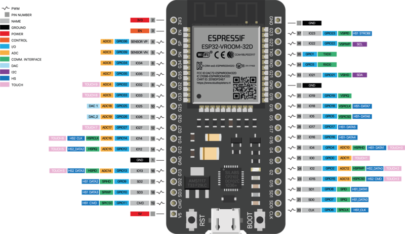
ESP32 Devboard 38pin version: | ESP32 Devboard 38pin version: | ||
Nice ESP32 Devboard 38pin documentation >> https://www.studiopieters.nl/esp32-pinout/ | |||
http://hyperdramatik.net/mediawiki/images/thumb/a/aa/ESP32-38_PIN-DEVBOARD.png/800px-ESP32-38_PIN-DEVBOARD.png | |||
=Programming the ESP32 Devboard from the Arduino IDE= | =Programming the ESP32 Devboard from the Arduino IDE= | ||
| Zeile 7: | Zeile 9: | ||
== | ==add link to board manager URL== | ||
Menu: Preferences —> Additional Boards Manager URLs: | Menu: Preferences —> Additional Boards Manager URLs: | ||
| Zeile 14: | Zeile 16: | ||
== | ==install board== | ||
Menu: Tools —> Boards —> Boards Manager: | Menu: Tools —> Boards —> Boards Manager: | ||
| Zeile 23: | Zeile 25: | ||
== | ==das board und den port auswählen== | ||
Menu: Tools —> Board: ESP32 Dev Module | Menu: Tools —> Board: ESP32 Dev Module | ||
| Zeile 32: | Zeile 34: | ||
== | ==open example: blink an LED== | ||
open example code | open example code | ||
| Zeile 42: | Zeile 42: | ||
edit: LED_PIN = 2; | edit: LED_PIN = 2; | ||
===upload code=== | |||
Tip: sometimes you need to press and hold the BOOT button on the ESP while the Arduino IDE is trying to program. | |||
“Hard resetting via RTS pin…” means the upload was successful | |||
===connect LED=== | |||
—> connect an LED between GPIO pin 2 and GND (!make sure it is ground and not CMD!) | —> connect an LED between GPIO pin 2 and GND (!make sure it is ground and not CMD!) | ||
| Zeile 51: | Zeile 58: | ||
==example: reading analog sensor value== | |||
OPEN EXAMPLE: Menu: File —> Examples —> Communication —> “Graph” | OPEN EXAMPLE: Menu: File —> Examples —> Communication —> “Graph” | ||
| Zeile 57: | Zeile 64: | ||
edit: Serial.begin(115200); | edit: Serial.begin(115200); | ||
edit: pick a GPIO pin with | edit: pick a GPIO pin with an ADC | ||
(GPIO = General Purpose In Out) | (GPIO = General Purpose In Out) | ||
| Zeile 65: | Zeile 72: | ||
for example: analogRead(34); | for example: analogRead(34); | ||
// Note: "ADC2 pins cannot be used when Wi-Fi is used. So, if you’re using Wi-Fi and you’re having trouble getting the value from an ADC2 GPIO, you may consider using an ADC1 GPIO instead, that should solve your problem." | |||
// Note: ADC2 pins cannot be used when Wi-Fi is used. So, if you’re using Wi-Fi and you’re having trouble getting the value from an ADC2 GPIO, you may consider using an ADC1 GPIO instead, that should solve your problem. | |||
===upload=== | |||
Tip: sometimes you need to press and hold the BOOT button on the ESP while the Arduino IDE is trying to program. | |||
“Hard resetting via RTS pin…” means the upload was successful | |||
===connect analog sensor to pin 34=== | |||
remeber to build a voltage divider! | |||
===open serial monitor=== | |||
you should see 6 analog sensor value printed in one line, plus the two values: “0” = min and “4095” = max | |||
Aktuelle Version vom 3. Mai 2022, 17:08 Uhr
ESP32 Devboard 38pin version:
Nice ESP32 Devboard 38pin documentation >> https://www.studiopieters.nl/esp32-pinout/
Programming the ESP32 Devboard from the Arduino IDE
Um den "ESP 32 Dev Module" programieren zu können müsst ihr in Arduino folgende schritte machen:
add link to board manager URL
Menu: Preferences —> Additional Boards Manager URLs:
https://dl.espressif.com/dl/package_esp32_index.json
install board
Menu: Tools —> Boards —> Boards Manager:
search for: “ESP32”
Install: “esp32 by Espressif Systems”
das board und den port auswählen
Menu: Tools —> Board: ESP32 Dev Module
Menu: Tools —> Port: dev/cu…
(unplug and plug to see which port appears)
open example: blink an LED
open example code
Menu: File —> Examples —> Basics —> “Blink”
edit: LED_PIN = 2;
upload code
Tip: sometimes you need to press and hold the BOOT button on the ESP while the Arduino IDE is trying to program.
“Hard resetting via RTS pin…” means the upload was successful
connect LED
—> connect an LED between GPIO pin 2 and GND (!make sure it is ground and not CMD!)
connect an LED between GND and pin 2
the LED should blink on and off
example: reading analog sensor value
OPEN EXAMPLE: Menu: File —> Examples —> Communication —> “Graph”
edit: Serial.begin(115200);
edit: pick a GPIO pin with an ADC
(GPIO = General Purpose In Out)
(ADC = Analog Digital Converter)
for example: analogRead(34);
// Note: "ADC2 pins cannot be used when Wi-Fi is used. So, if you’re using Wi-Fi and you’re having trouble getting the value from an ADC2 GPIO, you may consider using an ADC1 GPIO instead, that should solve your problem."
upload
Tip: sometimes you need to press and hold the BOOT button on the ESP while the Arduino IDE is trying to program.
“Hard resetting via RTS pin…” means the upload was successful
connect analog sensor to pin 34
remeber to build a voltage divider!
open serial monitor
you should see 6 analog sensor value printed in one line, plus the two values: “0” = min and “4095” = max